DIY Kits Butterfly Music Flash Lamp Kit 38 LEDs Flashing Light Suite 4-5V for Birthday Gift


Here is my youtube video covering details about this project:


Here is the Hindi Urdu version of the same circuit build video on my youtube channel:


Function:
This circuit consists of 38 LEDs to form a butterfly image. Among them, 14 red LEDs form the middle heart, and 24 white LEDs form the two wings of the butterfly.
The red heart is always on and the white wings will continuously flash to display flying effect. In the meantime, the buzzer will sound the song of “Happy Birthday to You”


Principle:
When power on, the two triodes VT2, VT3 will compete to connect. Since there is difference among components, only certain one triode will be connected firstly.
If VT3 is firstly connected, then VT3 collector voltage will decrease, LED1-12 and LED27-38 will be on. The right port of the capacitor C2 is close to zero voltage;
because the two ports voltage of the capacitor cannot change suddenly, VT2 base will become zero voltage nearly (or negative voltage, if original C2 has power), and VT2 will close.
With the C2 charging by resistor R3  (usually C2 discharge via R3), triode VT2 base voltage will increase;
when it is higher than 0.6V, VT2 will be connected from cut-off status and the collector voltage will decrease then close to 0V.
At the same time, with the decreasing of triode VT2 collector voltage, the triode VT3 base voltage will decrease too under the effect of capacitor C2. VT3 will be cut-off from connected status and all the white lamps are off.
Then cycle it, the two triodes in circuit will be alternatively connected and cut-off so that the wing LED will flash all the time. Changing the resistance value of R2, R3 or the capacitance can change the flashing speed.
Changing the resistance value of R4 and R5 can change the brightness of LEDs. The IC is music diode, it defaults “happy birthday to you”, you can change it to other music diode according to your needs.
The music sounded by triode is amplified by VT1 and drive the buzzer.

Notice:
1.All components should be installed close to the board surface
2.When you cut the pin, please do not pull the pin forcefully; otherwise, it will cause open circuit
3.All the LED directions should correspond to the symbol
4.Power voltage should be 3-5V. Usually red, yellow, green LEDs adopt 3V power supply, and the white, blue LEDs adopt 4-5V power supply

Parameter:
NO.ParameterValue
1NameMusic flashing lights
2Operating VoltageDC 4-5V
3PCB Size50*127mm
Component List:
NO.Component NamePCB MarkerParameterQTY
1Metal Film ResistorR11K1
2Metal Film ResistorR230K1
3Metal Film ResistorR347K1
4Metal Film ResistorR4,R510ohm2
5Electrolytic capacitorC1,C222uF2
6S8050VT1-VT3TO-923
79300IC1TO-921
8Buzzer1
9White LEDL1-L12,L27-L385mm24
10Red LEDL13-L265mm14
11PCB50*127mm1
NOTE:You can complete the installation by PCB silk screen and component listing.

Finished Product Picture:


Continue reading

Cordless Rechargeable soldering iron


This post is shared only for educational and learning purpose. This is not sponsored.


Here in this above image you can see a soldering iron which is battery operated and it is cordless. You can charge its battery and can take it with you anywhere and perform soldering anywhere without the headache of electricity. There is no risk of electric shock too. Regular soldering iron is a dangerous tool which killed many technicians. The reason is as this tool is very frequently used by technicians and it is in the hand electrified. In this situation if its element is breaking down and is touching to its metal body, and a person is soldering with it; it could kill or serious injury and fatal accident could occur in such a situation. The battery operated cordless soldering iron totally eliminates this risk and is providing nice and clean safe job to a service technician or service engineer. Electronics repair itself is a difficult and cumbersome job. This is a must that a technician or a service engineer must have good and reliable tools to perform the good quality job with ease. There are different kind and types soldering irons.

iso-tip 7700 cordless soldering iron is one of them. This is iso certified and specified soldering iron. Amazon is selling different kind and types of soldering irons. They have cord type as well as cordless type soldering iron from different manufacturers. One of the best soldering iron manufacturer out there is Weller. Weller is German brand soldering iron which is a bit expensive but very reliable and durable. They have both cord type and cordless type soldering irons available. There soldering irons are of industrial standard. They have very nice and accurate temperature control. They have Hakko type tip replacement arrangement. This soldering iron or soldering station is coming with different tips. One can select a suitable tip according to the job condition and requirements.

Now a days with smd surface mount device technology there are UV soldering stations and hot air soldering and desoldering guns are used. They became very popular with the invention of modern computers, laptops, tablet computers and cell phones. As these all modern electronics have smd technology used in them, their repair needs hot air desoldering and uv station de soldering and soldering.Professional solder and de-soldering stations are very expensive which uses IR or infra red waves to solder or de-solder the job. But hot air stations became inexpensive especially from chinese manufacturers.
Continue reading

Delay automatic on timer circuit testing and power up.


Timer circuit testing


Here is youtube video English version on this subject:


Here is youtube video Hindi/ Urdu version on this subject:


The timer circuit which we discussed before in the last post which is here can be tested using power supply and some arrangement.

Here in the following lines I will discuss how to test the circuit. This delay automatic on circuit can switch on the power with delay of  a few seconds to a few minutes. The delay time can be adjusted using a potentiometer or changing the timing capacitor if a big duration of the time is required. This circuit is especially made for creating on delay for refrigerators, freezers and air conditioners. As these units are sensitive for ON and OFF. The refrigeration and air conditioner machine should not be switched on immediately after switch off. Instead there must be a delay of a minute to a few minutes say three minutes in most cases between off and on. Otherwise the compressor may damage or get serious defect if switched on immediately after switched off.

This delay automatic  on circuit is design in the way to automatically give a delay of specified time of a minute or a few minutes which is preset on every switch on. If this unit is installed with refrigerator or air conditioner machine, it will protect it from immediate switch on after every switch off due to power failure or any reason.

As power failures are very common now a days in our country hence problems to refrigeration system or to air conditioners are also very common due to such power cuts. The remedy is not very difficult or complex but us of such a timer! So in the next posts I will show how to connect it to a refrigerator or to an air conditioner to solve such problem and prolong the compressor life for such machines.

Here are a few images in which I will show how to power up and test such a circuit on a work bench to ensure and understand the function of such a timer.


Grab the circuit and locate the power supply connections for the circuit. Also look for the output or control of the circuit to understand the function of the circuit.


Take to appropriate length of hock up wire pieces and solder them on the power supply terminals to power up the circuit with required voltage which is 9 to 12V in our case.


Set up the meter to DC voltage and set the meter probes to V and Common terminals to measure the power supply DC voltage.


Measure the DC output voltage of the power supply or supply adapter to ensure the right voltage supply to the circuit which is 9.67V in our case.


Power up the circuit and look at the function of the circuit. We noticed that first the Green LED came then in a second or two the Red LED also switch on with a relay click. This ensured the timer function with time adjusted to very little delay of a second or two.


Change the multimeter to continuity and ensure the relay switching terminals continuity after powering up. You will see that the relay is changing the contact state after the timer completes the delay.


Adjust the time delay to the required delay time using a screw driver and adjust the potentio meter with the help of that screw driver. We set the time for above a minute to see the function of the timer.


If you require even more time delay from the circuit which could not be obtained even with the help of the potentio meter, you can replace the timing capacitor 330Uf in our case to some higher value say 470Uf or 1000Uf for larger delay time.


Hope this guide may give you understanding about the circuit operation as well as the circuit live understanding. If you didn't watched the video associated with this blog post, watch it now to get more understanding.

In the next blog post and video I will show how to install this circuit in practical way and how to get benefit from it with your refrigeration or air conditioning system to protect them from damage using such a timer. All you should do is stay tuned, subscribe on my channel and share my videos and blogs with your friends.

Continue reading

Relay in Electrical control and power system

Relay in Electrical control and power system


Relay 

Relay is a very important device or component used in electrical and electronics systems. Relay is used always everywhere. If this is house hold, Automotive, Industry, Locomotive, plane or any other electrical system; relay will be everywhere.

Relay have different types and shapes. They are basically electro-mechanical or electromagnetic devices used in all electrical or electronics systems. Relay basically acts like a switch which is electrically controlled. In very simple form a relay it can be single pole single through type. In which there could be a pair of contacts making a normally open or normally closed switch which could be activated by an electromagnetic coil and a spring.

How a Relay functions

 A relay is working like a switch. The ordinary switch is activated through your finger whereas a relay is activated through electromagnetic coil and is activated electrically. There is one electromagnetic coil in a relay which activates a switch. The coil is energized or magnetized through electricity. The electricity to the coil can be AC or DC. The voltage value depends upon the relay design. There are different voltage values for relay coil like 5V, 12V, 24V, 48V, 110V or 220V AC or DC depends upon the situation and requirement. This is important to use specific relay with specified coil voltage on that same voltage value otherwise the relay coil may damage.

There is another important parameter for a relay is the relay contact current and voltage rating. This parameters again depends upon relay construction and requirement. There are different ratings like 5A, 10A, 15A, 20A, 50A, 100A, 120A etc. So you should use a relay under the specified current rating for a specific relay to keep it in safe operation condition.

Relay uses

 Relay is used everywhere in electrical systems. Relay is there in your TV, Refrigerator, stabilizer, car, changeover switch, power supply almost everywhere you can think of. The relay is used in all automated systems where switching is occurred. It is a must for everybody to understand a relay. If you understand one relay, others will become easy for you. So it is better to understand any relay so that you will be able to understand many other as well.

Relay price

 Relays are in different price range. You can purchase any relay of your choice or requirement. It starts from 5 relays a $ to $$$ a relay! Good news is household relays are not very expensive. You can get them for very low cost. The one which I used in this project is 1$ relay.
 
Continue reading

Timer circuit reverse engineering


Here is the Youtube video English version associated to this article:


Here is the youtube video Urdu version:


What is reverse engineering?

Reverse engineering is a term used to dig behind the idea or the concept at which something is build. The reverse engineering reveals the basics of a system on which the system is built.

In Electronics the reverse engineering is used to breakdown a build circuit in its basic schematic circuit diagram. This is done to translate the circuit from original system to paper. Once the circuit is got on paper, it is easy then to copy it, circulate it, modify it or enhance it after studying it in detail.

The reverse engineering of small circuit is easy to copy it to paper part by part and note down the components values with care. Anyhow sometimes it is very difficult to understand a pre build circuit when there transformers, some complex coils or some custom made components are used in a circuit. Also it becomes more troublesome when double sided or multi-layer PCB is used. In such a case the best way is to get the concept from a system and design your own circuit with your own concept and idea having same functionality. Anyhow it needs much more knowledge, skill and facility.

Here in the following lines I will show important steps how to reverse engineer a small and simple timer circuit. The circuit itself is very low cost like 1$ but the important thing is to get the concept used in it. Because if one know the concept and the schematic of this circuit, it can be used in big system or circuit when there would be a need.

To reverse engineer a circuit you should know its function, its input, output and supply voltage details. When you have all these details, right them down on a paper and start reverse engineering the circuit details. All the components values you must mention clearly on the paper diagram. All the line connections you should make clearly and take care of jumping wires and connections.

Reverse Engineering the delay automatic on timer board:

Look at the board and count the components carefully. The count will help you to summarize your work and give you help in troubleshooting your work mistakes if happen any.


Look at the copper side of the board also and give a little attention to connections and traces.


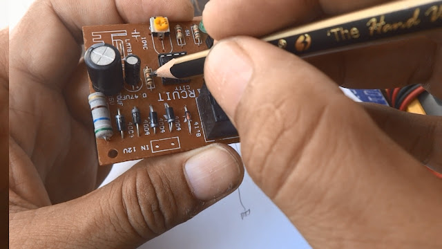
Locate the pin no. 1 of the IC. Also look for the IC number. Then start tracing from IC pin no. 1 where that particular pin is connected. The IC have a notch above pin 1 as you can see in the image blow.


Look that the pin no. 1 trace is connected to the the two solder connections here where I am pointing by pencil. Also the PCB trace is further connected somewhere. We will give attention to all connections to this point.


Upon inverting the board direction, we found that these two soldering connections are two diodes anodes. The diode number where 1N4004. Here we can see four diodes and they form a bridge rectifier. The two anodes junction is negative side supply rail on DC side after bridge rectifier.


Now we are going to draw the pin 1 connection on the paper at IC block. The pin 1 is grounded or connected to negative supply rail.


Now we are giving attention to pin 2. To the pin two a resistor is connected. The resistor value we can calculate from its color code. The resistor color code we will cover in some blog and in some Youtube associated video.


Mention the resistor value that is 18K on the paper with pin 2 on IC block.


Then the next component connected to pin 2 is an electrolytic capacitor. The electrolytic capacitor have two values. Its capacitance in Uf and working DC voltage in Volts. take care of both values.


Mention both values representing the electrolytic capacitor on the paper.


In this way populate all circuit schematics with components and connections with their corresponding values and other details where necessary.


Here is a redrawn circuit schematics using window drawing software. This drawing will give more clear image of the same circuit.


Continue reading

Blue Digital LCD Display Voltmeter Ammeter Power Meter AC 80-260V 20A/4400W


Here is my youtube video showing details of such product in video:


Here is the Urdu Hindi version of this instrument review on Youtube:


You can buy this product on ICStation.com the link is here below:
http://www.icstation.com/blue-digital-display-voltmeter-ammeter-power-meter-260v-20a4400w-p-11981.html

Product Introduction:
1.Operating Voltage:AC 80-260V
2.Testing Voltage:AC 80-260V
3.Rated Power:20A/4400W
4.Operating Frequency:45-65Hz
5.Measurement Precision:1.0 level
6.Connection Picture:


Function:

1.Electric parameter measurement function (voltage,current,active power,electric energy)

2.Operating time function (record load accumulated operating time)
3.Overload alarm function (if it is over power alarm threshold,the backlight will
  flash and sound an alarm)
4.Power alarm threshold preset function (users can set power alarm threshold freely)
5.Electricity quantity,operating time key clear function
6.Backlight function
7.Power failure data saving function (save accumulated electricity before power failure,
  operating time,display item,backlight state)
8.Large screen LCD display function (display voltage,current,electric energy,active power,
  accumulated operating time)

Kep/LCD Function:
UP:1.In normal display state,if short press it,and it will cycle display time,power,
     electricity quantity,current,voltage in reversed sequence.
   2.If short press it,then the digit will decrease 1 in power alarm threshold setting state.
   3.If short press it,it will quit the clear state when electricity quantity and time
     have been cleared.

DOWN:1.In normal display state,if short press it,and it will cycle display voltage,
       current,electricity quantity,power and time.
     2.If short press it,it will decrease 1 in power alarm threshold setting state.
     3.If short press it when electricity quantity and time have been cleared,then
       it will quit clear state.

SET:1.If long press the key for 3s in power display state,then it will enter into
      power alarm threshold setting state.
    2.If long press the key for 3s in electricity quantity or time display state,
      then it will enter into electricity quantity or time clear state.

OK:1.If short press the key,it will open or close the backlight in normal display state
   2.If short press the key,it will switch set digit in power alarm threshold setting state.
   3.If short press the key in electricity quantity or time clear state,then it will
     clear electricity quantity or time and quit the clear state.

Power overload threshold setting:
1.In normal display state,it will switch into power display value if press UP or DOWN key.
2.If long press the SET key for 3s,the screen will flash;then loosen the key.
3.Defaults the first digit (thousands place)on the left flash;this number can be changed
  through short press UP or DOWN key;short press the OK key will finish this digit and
  enter into next digit setting;from left to right are thousands' place-->hundreds' place-->tens' place-->ones' place;
  after ones' place has been done,press OK key to finish the overload threshold setting,LCD screen
  will back to POWER display item.
4.Overload threshold maximum power is 9999W;if the overload threshold is over this limit vlaue,
  then the LCD screen will display ERR prompt;and it will back to overload setting interface and repeat setting after 3s.

Accumulated time,electricity quantity clear setting:
1.If press UP or DOWN key in normal display state,it will switch into accumulated time or
  electricity quantity manu.
2.If long press the SET key for 3s,the screen will flash;then loosen the key
3.If short press the OK key,the accumulated time or electricity quantity data will be cleared,
  and LCD screen will back to accumulated time or electricity quantity display item;if users don't want it
  cleared,short press the UP or DOWN key;then it will quit clear state and back to manu display.

Backlight function:
1.After power on,the backlight will be automatically on;if short press the OK key in normal
  display state,it will open or close the backlight.The backlight state has memory function;
  that is to say that it will recover on/off state before power failure when power on again.
2.When the load power is higher than setting overload power threshold,the backlight will flash
  and sound an alarm;when the power value is lower than overload power threshold,the backlight
  will stop flashing and recover previous backlight state.

Manu display:
1.After power on,it defaults display power;if short press the UP key,then it will cycle display
 time,power,electricity quantity,current,voltage in reversed order;if short press the DOWN key,
 it will cycle display voltage,current,electricity quantity,power,time in order.
2.When the load power is higher thant alarm threshold,then it will back to power display manu
  and then flash and alarm.
3.Manu display has memory function;that is to say it should recover display items before
 power failure after power on again.


Notice:
1.This module can be used in indoors not outdoors.
2.The load can not be over rated power.
3.The connection sequence can not be false.


translate to hindi translate english to malay google translate in hindi translate english to chinese translate english to german google translate camera translate english to italian bing translator meter definition english meter measurement define metre meter symbol meters conversion chart meter definition music meter definition poetry meter or metre digital electric meter hack india how to slow down digital electricity meter how to slow down an electric meter stop electric meter with magnet how to stop a digital electric meter hack digital electric meter tutorials stop electric meter with remote digital electric meter hack with remote digital electric meter hack in pakistan digital meter hack electricity in pakistan 2017 how to hack digital electric meter by remote stop power meter pakistan electricity meter 1st video how to slow down digital electricity meter kesc digital meter slow how can i stop digital electric meter digital electric meter hack india how to slow down digital electricity meter digital electric meter hack india how to slow down an electric meter stop electric meter with magnet digital electric meter hack with remote how to stop a digital electric meter stop electric meter with remote hack digital electric meter tutorials smart meter hack magnet


Continue reading