Samsung S7 Edge SM-G935F service manual

 Samsung S7 Edge SM-G935F service manual

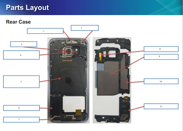
Here is the rear parts for Samsung S7 Edge SM-G935F mobile phone

Samsung S7 Edge SM-G935F service manual

 Samsung S7 Edge SM-G935F Parts description


  1. WIFI ANT2(5GHz only)
  2. WIFI ANT1 
  3. 12M CAM 
  4. FLASH LED + HRM SENSOR
  5. WPC ANT (NFC + MST + Wireless charing) 
  6. SPEAKER
  7. MAIN ANT 
  8. WPC ANT Contact 
  9. GRAPHITE SHEET 
  10. GRAPHITE SHEET 
  11.  SPEAKER 

Continue reading

What is a Circuit Breaker? Vacuum circuit breaker working function

 What is a circuit breaker?

A circuit breaker is an electrical device that is used to interrupt electrical power. A circuit breaker is like a heavy switch that is used to switch on and off heavy electrical power. A special arrangement is made to quench the arc produced between switching contacts during circuit interruption. For the purpose of arc quenching, air, sf6 gas, or vacuum is used in the circuit breaker.

Types of circuit breaker

A circuit breaker is categorized in many ways. Different types of circuit breakers are used according to needs and requirements.

Circuit breaker types according to voltage

LV circuit breaker

LV circuit breaker is used on low voltage to interrupt electrical power. Air is normally used as arc quenching media in such kind of circuit breakers.

MV circuit breaker

MV circuit breakers are used to interrupt medium voltage in industry and power distribution substations. Vacuum and oil are used as arc quenching media in such kind of circuit breakers.

HV circuit breaker

HV circuit breakers are used to interrupt very high voltage power. SF6 gas is used as quenching media in such kind of circuit breakers.


Parts of Circuit breaker

There are many parts of a circuit breaker. A circuit breaker is a piece of complex electrical equipment having many parts like contacts, springs, levers, hinges, and many other parts. The following diagram shows common parts for a circuit breaker.
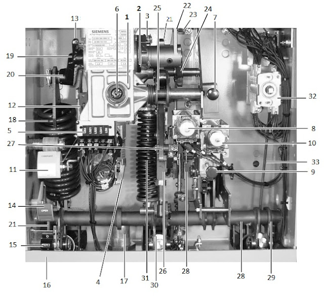
Circuit breaker parts
  1. The Charging mechanism of the gearbox
  2. The Charging flange
  3. The Driver
  4. The Spring charging motor
  5. The Limit switches
  6. The Manual spring charging port
  7. The Close pushbutton
  8. The Close coil 52SRC
  9. The Open pushbutton
  10. The trip coil 52T
  11. The Closing spring charge indicator
  12. The Linkage
  13. The Control lever
  14. The Close-open indicator
  15. The Operation counter
  16. The Operator housing
  17. The Shock absorber
  18. The Closing spring
  19. The Charging shaft
  20. The Crank
  21. The Cam disc
  22. The Lever
  23. The Pawl roller
  24. The Close latch pawl
  25. The Drive lever
  26. The Trip free coupling rod
  27. The Spring return latch
  28. The Trip free coupling lever
  29. The Jackshaft
  30. The Lever - phase C
  31. The Lever - phase B
  32. The Lever - phase A
  33. The Opening spring
  34. The Auxiliary switch
  35. The Auxiliary switch link
Continue reading

3 phase power and 3 phase power generator

 3 phase power and 3 phase power generator

3 phase power generator

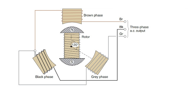
 3 phase power generator is a machine which generates 3 phase ac power. AC power is of two types. One is single phase and the other is multi phase. 3 phase is example of multi phase power which is very commonly used due to its special characteristics and powerful nature over single phase ac power. 3 phase power is generated in the same way as single phase power is generated. Only difference is the construction of 3 phase ac power generator. There are three seperate windings 120 degree apart each other. In a 3 phase power generator 3 windings are places 120° apart to make a complete machine having 3 separate windings in total of 360°. 

RMS value of a sin wave signal

Sin wave graphical presentation

A vector V is rotated in a circle completing 360 degrees. In this way the vector is passing through a sin wave as shown in the figure above. At the moment the vector is passing through 45 Degrees. At angle 90 degrees the vector passes through its maximum value. and at 180 degrees & 360 degrees the vector passes through its minimum value.

3 phase power generation

3 phase power generation

In the figure above, the generated emf or voltage is at maximum on the brown phase. The voltage of emf is increasing on the black phase. Whereas voltage or emf is decreasing on the gray phase. As you can see there are three sin waveforms each 120° apart. If all 3 phase power is added together, the vector sum would be zero. This is what is the 3 phase.

Continue reading

Components of three-phase squirrel cage induction motor. Starting method.

 Components of three-phase squirrel cage induction motor to determine starting method

Parts of squirrel cage induction motor

Following are the main parts of a squirrel cage induction motor.

  1. Motor body or frame
  2. Stator
  3. Rotor
  4. Stator winding
  5. Stator core
  6. End covers
  7. Cooling fan
  8. Bearings
  9. Dust seals
  10. Terminal box
  11. Terminals
  12. Spacers
  13. Rotor short-circuiting rings
  14. Rotor bars
  15. Motor nameplate
  16. Stator cooling fins
  17. Mounting bolts
Parts of three-phase squirrel cage induction motor

Motor body or frame

The motor body or frame is the outer housing encapsulating all motor parts. Motor body or frame is made of cast iron and sometimes it is made of Aluminium to reduce motor weight. Motor body or frame provides housing for stator also.

Stator

The stator is the stationary part of the motor holding motor windings. Motor windings are used to produce a three-phase rotating magnetic field to rotate the station located inside the stator. There is an air gap maintained between the rotor and stator so that rotor can rotate inside the stator minor gape without touching each other.

Rotor

The rotor is the rotating part of the squirrel cage induction motor. The rotor is made of metal sheet laminations bind together to reduce eddy current and hysteresis losses. The rotor is mounted inside the squirrel cage motor with the help of bearings in a way that the rotor can rotate freely inside the minor air gape of the stator. The rotor has bars in it that are short-circuited with the help of short-circuiting rings on both sides. The bars inside the rotor are arranged like a cage which resembles the cage made for squirrels. So that's why the name squirrel cage has been given to such a kind of motor.

Stator windings

Stator windings are a very important part of a squirrel cage induction motor. The windings are used to produce a three-phase rotating magnetic field inside the squirrel cage motor. There are two types of connections for a three-phase motor winding. Star connections and delta connections. The rest there are many types and details about three-phase windings for squirrel cage induction motors. Windings are made of insulated copper wires. Sometimes aluminum wires are also used to reduce weight and cost. Copper windings are places inside slots that are paper insulated. The windings are interconnected on the end of the windings.

Stator core

The stator core is made of silicon steel or an electrical sheet that provides housing for windings and provides a path to magnetic lines of forces or magnetic flux. The stator core has slots to place windings inside. Also, windings are insulated with the help of insulating paper of Myler paper to avoid winding shorting to the ground or motor body.

End covers

Motor end covers are used to pack the motor from the sides. Also motor end cover has bearing housing to center the motor shaft in the middle. Motor end covers also provide arrangements for bearings lubrication and greasing.

Cooling fan or cooling disk

A cooling fan or cooling disk is provided on the free side of the motor which propels air toward the motor body fins to keep the motor cool. Big motors have special arrangements for motor cooling and also motors that run with VFD have a separate motor for cooling the motor. The cooling fan is made of both plastic and sometimes metal.

Bearings

Bearings are mounted on both sides of the squirrel cage induction motor. The shaft is mounted inside the bearings to make sure the uniform air gap between the stator and rotor. Also, bearings provide freedom of rotation to the motor shaft. In big motors, more than two bearings are used. Sometimes there are two bearings on the drive end side and one on the free side or non-drive end side of the motor.

Dust seals

Dust seals are located in both end covers. Dust seals prevent dust entry in the motor and preventing the motor bearings from premature failure. Dust seals also keep the grease inside the bearings and preventing it from leaking. In some poor design motors, dust seals are not provided instead bearings end shield acts like dust seals.

Terminal box

The terminal box encapsulates the motor terminal block. On the terminal block, motor connections are made. The motor terminal box ensures insulated covering on the motor terminals and they are mounted in such a way that the motor terminal box cover can be opened or closed any time to make connections or disconnections with the motor.


Continue reading

INVEREX FRONIUS SYMO 5.0 & 20.0 KW

Inverex FRONIUS SYMO 5.0 & 20.0 KW

Inverex Fronius Symo series is the 3 phase inverter series for large power requirements. Inverex Fronius Symo power ranges from 5KW to 20KW. Inverex Fronius Symo produces three-phase pure sine wave power which could be used as an alternative to the line three-phase power. Inverex Fronius Symo uses the standard interface of LAN  Ethernet and WLAN WiFi for easy interfacing and control. Fronius Symo provides the best meter interface which shows very clear information of the energy consumption from different sources like Utility, Solar, and Battery. Also, the interface provides important data to user which helps the user to manage parameters.
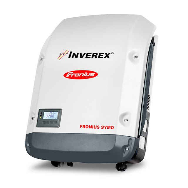
Inverex fronius symo 5.0 20KW


Continue reading

Audi rear wheel leaf spring for suspension

 Audi rear wheel suspension leaf spring

Audi rear wheel spring diagram:

Audi rear wheel suspension spring

Audi rear wheel spring components details:

  1. Rear spring shackle
  2. Bush
  3. Bush
  4. Washer
  5. Nut
  6. Rear spring shackle
  7. Washer
  8. Nut
  9. Bush No. 2
  10. Rear spring assembly
  11. Bolt
  12. Rear spring bumper
  13. U bolt
  14. Washer
  15. Nut
  16. Spring U bolt seat S/ A
  17. Bush
  18. Nut
  19. Bolt


Continue reading

Audi car rear wheel suspension components detail diagram and illustration

 Audi rear wheel suspension components diagram

Illustration:

Audi rear wheel suspension diagram

Components details and description:

  1. Bush
  2. bush
  3. Rear spring shackle
  4. Rear spring shackle
  5. Bush No. 2
  6. Rear spring assembly
  7. U bolt
  8. Rear spring bumper
  9. Spring U bolt seat S/ A
  10. Washer plate
  11. Cushion
  12. Washer plate
  13. Cushion
  14. Washer plate
  15. Rear Shock absorber
  16. Washer plate
  17. Bush
  18. Washer plate
  19. Actuator
  20. Dust seal
  21. Bracket
  22. Washer plate
  23. Rear-axle housing
  24. Rear-axle bearing retianer

Continue reading

The Manual transmission for manual car

 The manual transmission used in manual cars

The manual transmission schematic diagram and illustration:
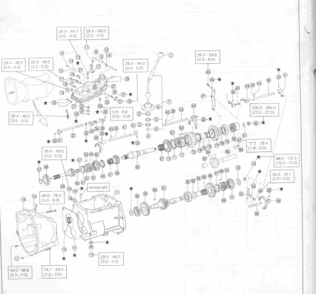
Following is the schematic diagram and illustration for a manual transmission used on most manual cars.

The manual transmission used on manual car

Components details for manual transmission used on most manual cars:

  1. Shift lever knob
  2. Snap ring hole
  3. Shift lever ball seat
  4. Shift lever boots
  5. Shift lever ball seat
  6. Bush
  7. Shift lever Ay
  8. Hose
  9. Clamp
  10. Union
  11. Bolt
  12. Hanger
  13. 5th Shift arm pivot
  14. Shift interlock No. 1 pin
  15. Shift interlock No. 2 pin
  16. Clamp
  17. Back-up lamp switch
  18. Clamp
  19. Clamp
  20. Tight plug
  21. Mission case cover gasket
  22. Torsion spring
  23. Shift fork lock plate S/ A
  24. E ring
  25. Ball
  26. Compression spring
  27. Gasket
  28. Reverse restrict pin holder
  29. Transmission case cover
  30. Slotted pin
  31. Shift inner lever
  32. Shift lever shaft
  33. Snap ring shaft
  34. Reverse restrict pin
  35. Torsion spring
  36. Shift outer lever No. 1
  37. Shift lever housing bust cover
  38. 3rd & 4th shift fork
  39. Ball
  40. Compression spring
  41. 3rd & 4th shift fork shaft
  42. Gear shift head No. 2
  43. 1st & 2nd shift fork shaft
  44. 1st & 2nd shift fork
  45. Shift arm pivot
  46. Gasket
  47. Reverse shift arm
  48. Compression spring
  49. Reverse shift fork
  50. 5th & reverse shift fork shaft
  51. 5th shift head
  52. 5th shift arm
  53. Gasket
  54. 5th shift arm pivot
  55. 5th shift arm shaft
  56. 5th shift fork
  57. Hole snap ring
  58. Bearing
  59. Input shaft
  60. Bearing
  61. Synchronizer ring No. 3
  62. Synchromesh shifting key spring
  63. Synchromesh shifting key
  64. transmission clutch hub no. 2
  65. transmission hub sleeve no. 1
  66. Synchronizer ring No. 3
  67. Needle roller bearing
  68. 3rd gear
  69. Output shaft
  70. 2nd gear
  71. Synchronizer ring
  72. Transmission clutch hub no. 1
  73. Reverse gear
  74. Synchronizer ring
  75. 1st gear bearing inner race
  76. Needle roller bearing
  77. 1st gear
  78. 1st gear thrust washer
  79. Output shaft rear bearing
  80. 5th gear
  81. Conical spring washer
  82. Look nut
  83. Bimetal formed bush
  84. Reverse idler gear S/ A
  85. Rever Idler gear shaft
  86. Reverse idler stopper
  87. Bolt
  88. Bearing
  89. Counter gear
  90. Woodruff key
  91. Counter gear shaft
  92. Bearing
  93. 1st gear thrust washer
  94. 5th gear bearing inner race
  95. Needle roller bearing
  96. countershaft 5th gear
  97. Synchronizer ring no. 3
  98. synchromesh shifting key
  99. Transmission clutch hub no. 2
  100. Synchromesh shifting key spring
  101. Transmission hub sleeve no. 1
  102. Spacer
  103. Locknut
  104. Clamp
  105. Clutch housing
  106. Type S oil seal
  107. Transmission case gasket


Continue reading

Honda civic overhead components illustrated diagram, Honda repair service manual

 Honda civic overhead components illustrated diagram, Honda repair service manual

Honda Civic and Honda city overhead components illustration

Honda Civic Honda city overhead component


Honda Civic Honda city overhead components details

  1. Head
  2. Rocker arm assembly
  3. Exhaust camshaft
  4. Intake camshaft
  5. Exhaust camshaft gear
  6. Intake camshaft gear
  7. Camshaft key
  8. Spark plug well rubber seal
  9. Headcover gasket
  10. Camshaft plate
  11. Camshaft holder
  12. TDC sensor 1
  13. TDC sensor 1 O ring
  14. TDC sensor 2
  15. TDC sensor 2 O ring
  16. Camshaft cover bolts
  17. Camshaft cover bolts washers
  18. Camshaft cover bolts rubber seal

Head:

The Head is the most important part of the vehicle engine. The Head is used to cover the pistons. The Head contains necessary parts like valves, valve springs, valve seals, and valve locks. Also, the overhead cams are fitted on the top of the head. The Head is sealing the piston tops through the head gasket.


Rocker arm assembly:

Rocker arm assembly is used to push on valves to open them according to engine timing. Rocker arms have valve gape adjustment arrangement.

Exhaust camshaft:

An exhaust camshaft is used to open and close exhaust valves. For this purpose, lobs are created on the exhaust camshaft at specific intervals.

Intake camshaft:

An Intake camshaft is used to open and close Intake valves. For this purpose, lobs are created on the exhaust camshaft at specific intervals.

Exhuast camshaft gear:

Exhaust camshaft gear is installed at one end of the exhaust camshaft. Exhaust camshaft gear is driven by the engine and it rotates the exhaust camshaft at half of the engine speed.

Intake camshaft gear:

Intake camshaft gear is installed at one end of the Intake camshaft. Intake camshaft gear is driven by the engine and it rotates the Intake camshaft at half of the engine speed.

Camshaft Key:

The camshaft key ensures the firm fixation of the camshaft gear of the camshaft.

Spark plug well rubber seal:

These seals are used to seal the spark plug wells and camshaft cover to avoid engine oil leakage.

Headcover gasket:

A headcover or camshaft cover gasket is used to seal the cover to avoid engine oil leakage. This gasket should not be confused with the head gasket. The Head gasket is another item which is sealing engine compression against the head and cylinder.

Camshaft plate:

Camshaft plates are located at the end of camshafts. The purpose of camshaft plates is to induce a pulse in the TDC sensors to show the position of camshafts to the ECU or ECM or vehicle computer. According to which the ignition and the fuel delivery is set.


Continue reading