Toyota Prius car different ecu location

 Toyota Prius car different ECU location


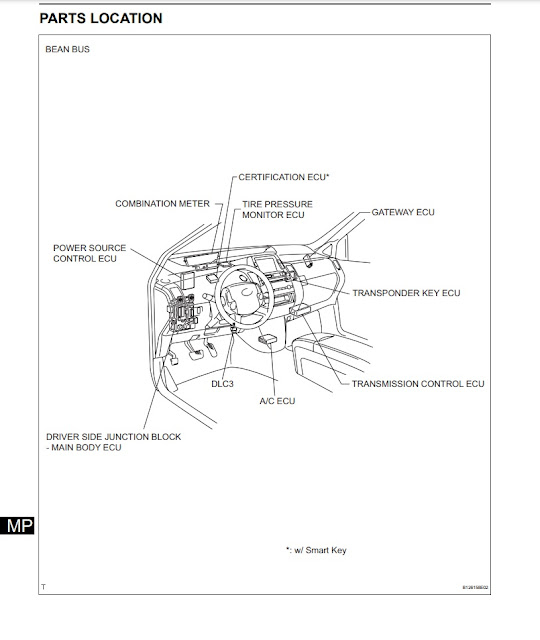
Location for different ECUs for Toyota Prius

Following schematic diagram depicting locations for different ECUs for Toyota Prius car. There are several ECUs installed for the Toyota Prius car to control various functions to ensure excellent driveability. ECUs communicated to each other using different communication methods depends upon their functionality and working. Toyota Prius is one of the most modern cars from Toyota and has complex electronics and electrical systems involved.
 
Toyota Prius different ECU location

Following are a few main ECUs found in the Toyota Prius car

  1. Certification ECU
  2. Combination Meter
  3. Power source ECU
  4. Tire Pressure Monitor ECU
  5. Gateway ECU
  6. Transponder Key ECU
  7. Transmission control ECU
  8. AC ECU
  9. SRS ECU
  10. Traction control ECU

Continue reading

Toyota Prius transaxle front suspension and drive shafts assembly

 Toyota Prius transaxle front suspension and drive shafts assembly Toyota Prius repair, service manual

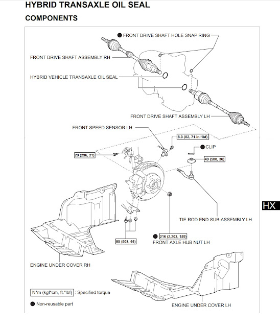
Toyota Prius transaxle and driveshafts diagram

Here in the following Toyota Prius transaxle and driveshaft schematic diagram is shown which is focussing on all parts associated with transaxles like axles, driveshafts, suspension, and wheel assembly. Hope this illustration would help many people who are about to repair their Toyota Prius themselves. Also, other small parts like driveshaft seals and the rest of the details are given.

toyota prius driveshaft transaxle and suspension
Toyota Prius driveshaft transaxle and suspension

Toyota Prius suspension and transaxle parts details:

Following are parts for Toyota Prius transaxle and driveshaft assembly:
  1. Snap ring for front driveshaft hole:
  2. Right-hand side assembly for the driveshaft
  3. Oil seal transaxle hybrid vehicle
  4. Left-hand side assembly for the driveshaft
  5. Left-hand side speed sensor front
  6. Clip for suspension
  7. Left-hand side subassembly tie rod end
  8. Left-hand side axle nut for the front wheel
  9. Right-hand side engine undercover
  10. Left-hand side engine undercover
Continue reading

Toyota Prius Toyota Hybrid cvt trans axle gearbox drive

 Toyota Prius Toyota CVT Hybrid transaxle transmission drive gearbox Toyota Prius repair, service manual

Toyota Prius real Toyota Hybrid:

Toyota Prius is one of the real hybrids cars from Toyota which is using hybrid technology and provides the best benefits and great savings on millage over the conventional vehicles of the same class. Toyota Hybrid is equipped with the latest technologies and it is a real modern car from Toyota which is truly hybrid. Toyota Prius uses CVT transaxle technology for drive train which is the best modern technology available on the market. Toyota Prius is cutting on fuel and providing test fuel economy with the best drive pleasure among the other manufacturers.

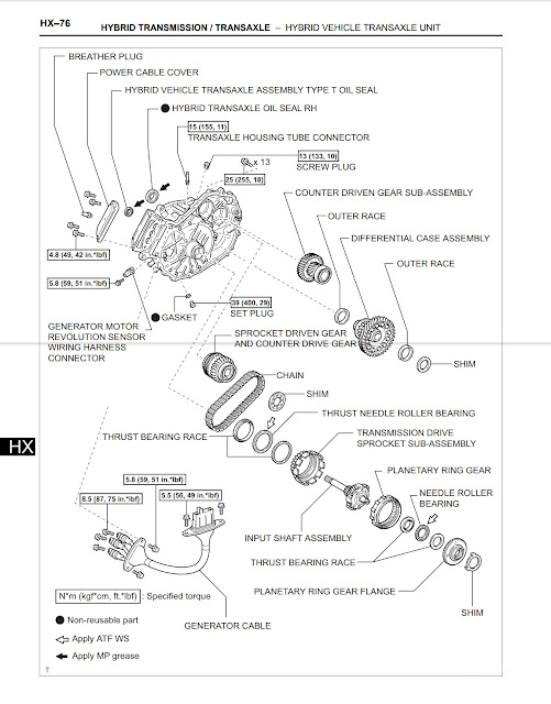
Toyota Prius Toyota Hybrid transaxle schematic diagram:

Following is the diagram for the Toyota Prius car transaxle. All parts are covers in detail to give a clear understanding of the Toyota Prius hybrid car transaxle.
Toyota Prius transaxle cvt schematic
Toyota Prius transaxle CVT schematic

Parts details for Toyota Prius CVT transaxle for a hybrid:

  1. Breathing plug
  2. Power cable cover assembly
  3. Type T oil seal for hybrid vehicle transaxle assembly
  4. Right-hand side oil seal for Hybrid transaxle
  5.  Tube converter housing of transaxle
  6. SCREW PLUG
  7. COUNTER DRIVEN GEAR SUB-ASSEMBLY
  8. OUTER RACE
  9. DIFFERENTIAL CASE ASSEMBLY
  10. OUTER RACE
  11. SHIM
  12. GASKET
  13. SET PLUG
  14. GENERATOR MOTOR
  15. REVOLUTION SENSOR
  16. WIRING HARNESS
  17. CONNECTOR
  18. SPROCKET DRIVEN GEAR
  19. AND COUNTER DRIVE GEAR
  20. CHAIN
  21. SHIM
  22. THRUST NEEDLE ROLLER BEARING
  23. TRANSMISSION DRIVE
  24. SPROCKET SUB-ASSEMBLY
  25. THRUST BEARING RACE 
  26. PLANETARY RING GEAR
  27. NEEDLE ROLLER BEARING
  28. INPUT SHAFT ASSEMBLY
  29. THRUST BEARING RACE
  30. PLANETARY RING GEAR FLANGE
  31. GENERATOR CABLE
  32. SHIM 


Continue reading

Toyota Prius Electrical wiring routing in engine bay part 1

 Toyota Prius Engine bay Electrical parts detail part 1 Toyota Prius repair, service manual

Toyota Prius EM01R0U electrical components under the hood 

Toyota prius wiring routing and components


All components and sensor details for Toyota Prius EM01R0U

1 A/C Condenser Fan Motor

2 ABS & BA & TRAC & VSC Actuator 

3 ABS Speed Sensor Front LH 

4 ABS Speed Sensor Front RH 

5 Air Fuel Ratio Sensor (Bank 1 Sensor 1) 

6 Ambient Temp. Sensor 

7 Brake Fluid Level Warning SW 

8 Brake Master Stroke Simulator Cylinder Assembly 

9 Camshaft Position Sensor 

10 Camshaft Timing Oil Control Valve 

11 Circuit Breaker Sensor 

12 Compressor Assembly (Motor) Inverter 

13 Converter 

14 Converter 

15 Crankshaft Position Sensor 

16 Coolant Heat Storage Tank Outlet Temp. Sensor 

17 Coolant Heat Storage Water Pump 

18 Engine Coolant Temp. Sensor 

19 Engine Hood Courtesy SW

20 Front Airbag Sensor LH 

21 Front Airbag Sensor RH 

22 Front Fog Light LH 

23 Front Fog Light RH 

24 Front Side Marker Light LH 

25 Front Side Marker Light RH 

26 Front Turn Signal Light LH 

27 Front Turn Signal Light RH 

28 Front Washer Motor 

29 Front Wiper Motor 

30 Headlight Beam Level Control Actuator LH 

31 Headlight Beam Level Control Actuator RH 

32 Headlight Assembly LH 

33 Headlight Assembly LH 

34 Headlight Assembly RH 

35 Headlight Assembly RH 

36 Headlight LH 

37 Headlight RH 

38 Horn (High) 

39 Horn (Low)
Continue reading

Audi car spark plug design

Audi car spark plugs

The function of the spark plug in the Audi car

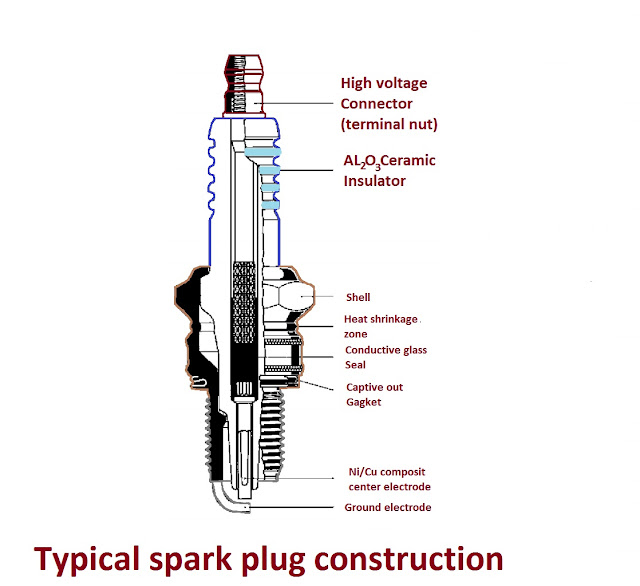
A spark plug is usually the end component of the ignition system in any petrol car. Spark plugs must be competent to withstand the high temperature and pressure of the combustion chamber. The ignition occurs billions of times during car engine start condition.

The ability to dissipate heat is the most important characteristic of the spark plug. The central electrode of the spark plug should be hot enough to burn out any carbon accumulation on it during the engine reaches the normal operating temperature. Also, the electrode should not be heated enough that it could burn the central insulator. The central insulator is very important as it separates the central electrode from short-circuiting to ground.
Typical spark plug construction


Cold spark plug

The cold spark plug is referred to as the spark plug which transfers the heat produced by the combustion process fast through the threads to the head of the engine from where it would spread to the cooling system of the car.

Hot spark plug

The hot spark plug is the spark plug that transfers the heat slowly from the combustion process through threads to the engine head from where the heat would be spread to the cooling system of the vehicle.

Types of spark plugs required for different Audi engines

Different engines require different spark plugs. The spark plug has different electrical and physical characteristics. Different manufacturers offer different spark plugs with different characteristics. As engine manufacturers specified the type of plug for their particular engine, it is better to replace the spark plug with the exact characteristics as the can engine manufacturer suggested and specified.

To ensure proper heat transfer from the spark plug to the engine head, it is important to tighten the spark plug into the engine head according to the torque specified by the factory. Values of torques are mentioned in the factory service and repair manuals.
Continue reading

Audi Car ignition system electrical circuit diagram

 Audi Car ignition system electrical circuit diagram

Audi Kettering or CB points ignition system

Kettering ignition system or CB points ignition system was the very common and popular ignition system for the last 100 years. This system was developed or invented by scientist Charles Franklin Kettering in 1906. The Kettering ignition system uses a battery, CB points, capacitor, and distributor for ignition. Before the Kettering system vehicles were using magneto ignition system. In a magneto ignition system, there is no battery and the voltage for the ignition system is produced by a small permanent magnet generator known as a magneto. Magneto ignition system is still used on small engines and motorcycles. Both magneto ignition and Kettering ignition system have their own benefits and limitations. All petrol engines need a spark to combust the air-fuel mixture. For combustion, a spark plug is installed in the engine cylinder head. When the piston reaches the top dead center during combustion stroke, a spark is supplied by the ignition system to combust the air-fuel mixture and an explosion takes place inside the engine cylinder which produces the mechanical power or torque.
Kettering ignition system point ignition circuit


Kettering ignition system working principle
  • Refer to the circuit diagram, when the ignition switch is moved to a close position, electrical energy flows to the primary winding of the ignition coil through the fuse.
  • When the contact breaker points close, the coil gets ground and current flows through the primary of the ignition coil. this flow of current creates a magnetic field around the primary coil.
  • Next, when the points open, the magnetic field collapses, and the energy of the magnetic circuit releases in the secondary coil of the ignition coil. This energy is in the form of high voltage and low current. This is due to the very high number of secondary coil turns of fine wire.
  • Those high voltages are enough to spark on the spark plug.
  • The spark produced is directed to the corresponding cylinder by the distributor. As it is a must to perform the ignition at right time, the distributor performs this job.
  • There is a need for spark advance. The reason for spark advance is needed at high engine rpm. At high engine rpm, the piston moves very fast inside the cylinder. This combustion of air-fuel mixture needs little time to take place. If the spark is applied at the top dead center at high rpm, there will be a delay due to air-fuel mixture combustion. This will degrade the engine performance at high rpm. To meed such a problem, a vacuum spark advancer is used which automatically advances the ignition timing at high engine rpm.

Audi Kettering ignition system and magneto ignition system advantages and disadvantages:


Magneto Ignition System
Advantages
Disadvantages
Advantages
Disadvantages
 Magneto systems don't need a battery to operate. This system generates its own energy. It is suitable for most small engines. The Kettering ignition system needs a battery to operate. Due to battery this system becomes expensive and needs to look after
As magneto is producing its own power. The generation is weak at startup due to less engine speed. This type of ignition has poor starting characteristics. Due to the high power available from the battery during startup, the starting is better and smooth
 In a magneto ignition system, few numbers of components are used which makes the system more reliable and low cost. In Kettering ignition much more components are used which makes the system more complex and complicated. Due to the complexity of the circuit more problems and defects could come in systems and the cost of the system increases.
As the engine speed increases, the generated voltage by magneto also increases due to to which the system performance increases. Kettering ignition system performance decreases with the high engine speed.
It needs multiple coil packs to fire in multiple cylinders for the Kettering ignition systemA single-coil pack with a distributor is enough to spark in multiple cylinders
Magneto systems are normally simple and reliable in construction. They need a permanent magnet, an ignition coil, a point or equivalent electronic switching arrangement to perform the job with simplicity and low cost. 

Kettering ignition system is obsolete now and is replaced with the modern computer or ECU controlled ignition system which needs multiple coils to fire in multiple cylinders.
 

Continue reading

Audi Le Mans quattro Sports car

Audi Le Mans Quattro Sportscar introduction

Audi le mans Quattro

Audi le mans Quattro is a very high-end Audi sports car with a V10 engine. Audi le mans Quattro is made on the concept of Audi R8 car. The Audi R8 won le mans 24 hours race three times. Audi le mans Quattro is an amazing machine which is the excellence of Audi corporation. Audi had produced Le mans Quattro with their years of experience on racing tracks. They developed this car with great effort and the latest technology.

Audi le mans Quattro engine and transmission

Audi le mans Quattro had installed a V10 Biturbo engine with a direct fuel injection system. This car is equipped with an LED headlight on the front whose front glass is clear and provides beautiful light at the night. Audi le mans Quattro is designed with craftsmanship that both the cockpit and passenger seats are perfectly matching the racing track needs. The engine for this car is a five-liter V10 FSI Biturbo engine which is capable of producing 449KW or 610BHP at 6800 rpm. The Audi le mans Quattro is producing a maximum torque of 750N.m of torque which remains constant from 1750 rpm to 5800rpm.
Audi le mans quattro
Audi le mans Quattro


Continue reading

Engine Management System for a V6 audi vehicle

 Engine Management system for Audi vehicle V6 engine

What is engine management system for audi?

Engine management system is a system in which an engine parameters are controlled electronically through different sensors and actuators to get optimum performance from the engine. Running a vehicle on less fuel and tune is for optimum performance is the key requirement for any modern engine. Consuming less fuel and burning the fuel totally in the engine to protect environment is the second achievement of the engine management system.

Types of sensors used for audi engine management system

There are two main types of sensors used on audi v6 engine for engine management system
They are input sensors and output actuators
Input sensors are collecting different parameters data like air quantity, air temperature, air flow, engine rpm, crankshaft position, camshaft position, coolant temperature, Oxygen quantity in exhaust gases and engine knock data etc.
The output actuators are controlling different quantities and parameters according to requirement and for best performance achievement. Such quantities are air, fuel, spark, oil, exhaust gas and many others. All sensors and actuators are connected to the engine computer or ecu which accepts data from different sensors and sending control signals to different sensor for optimum control and best resource utilization. following is a simple block diagram of a typical audi engine control system used on audi v6 engines.
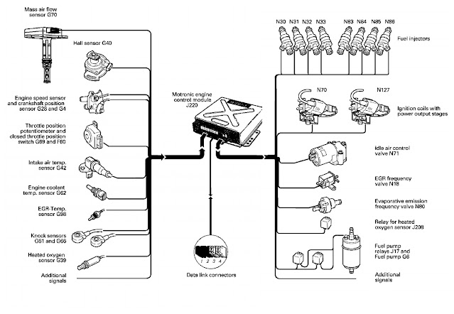
Audi v6 engine management system


Continue reading

Renault Kwid Review and specs


Renault Kwid Review and specs

General information about Renault Kwid

Renault Kwid is somewhat like a mini Renault Duster car. Renault Kwid is especially designed as a small engine and small car for average buyer and an average class family person. The Renault Kwid has 5 people capacity. The Renault kwid is coming in seven different variants in Petrol. The different variants of Renault Kwid had different engine size and some differences in transmission. Renault Kwid is equiped with beautiful LED head lights and LED tail lights. Renault Kwid is providing beautiful digital cluster and LED touch screen display which is 8 inch and it provides many features like all modern cars have. Renault Kwid car offers wide interior and configurable drive which is not provided by many competitors in hatchback class. The entry level Renault Kwid has 0.8 liter engine and provides 45hp of torque. Renault Kwid have a 184mm ground clearance which is enough for such class cars.
Renault Kwid
Renault Kwid


What is the price of Renault KWID Top Variant? What is the mileage of Renault KWID?

Prices detail have been given in the following table:

Std 0.8

799cc

22.3kpl

$4000

RxE 0.8

799cc

22.3kpl

$5000

RxL0.8

799cc

22.3kpl

$5500

RxT 0.8

799cc

22.3kpl

$5500

RxT 1.0

999CC

21.7kpl

$6000

RxT (O) 1.0

999CC

21.7kpl

$6000

Climber 1.0

999CC

21.7kpl

$6500

 What is the boot space in Renault KWID?

Renault Kwid has boot space of 297 liters.

Renault Kwid
Renault Kwid

What is the ground clearance of Renault KWID?

The ground clearance of Renault Kwid is 184mm which is enough for many cars.

Renault Kwid
Renault Kwid


Continue reading

PSN play store playstation store

 Playstaion store psn play station

Hot sales on psn and playstaion store

Hot deal 50%
Hot deal 50%

Continue reading

P0500 vehicle speed sensor malfunction OBDII code

P0500 Vehicle speed sensor malfunction

What is p0500 OBD 2 code

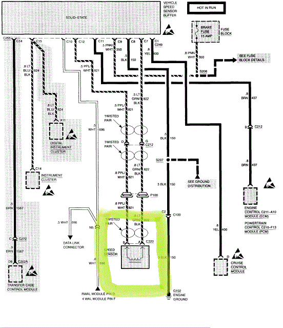
P0500 is a common code which causes check engine light to glow in modern vehicles. The code P0500 means Vehicle Speed Sensor Malfunction. P0500 code can come due to many reason and an automotive service engineer or technician should troubleshoot and diagnose such condition and dig behind the reason for P0500 trouble code. Tools like scan tool and oscilloscope is used to diagnose and troubleshoot the code p0500.

p0500 vehicle speed sensor code


p0500 trouble code definition

The code p0500 is a common obdII code which shows  a defect or malfunction detected in the vehicle speed sensor circuit. This code is associated with other trouble codes like p0501, p0502, p0503 etc.

What does the trouble code p0500 mean

The trouble code p0500 indicates fault found with vehicle speed sensor. The speed sensor sends pulses according to the vehicle speed to vehicle ecu or pcm. When these pulses are not received to the vehicle computer or ecu, the ecu or pcm sets the code p0500 and glow the check engine light which tells the driver that something is in trouble and need to check the system.

Why p0500 code comes?

There are a few reasons which causes p0500 code

  • Failed or defective vehicle speed sensor at drive gear
  • Loose connections in electrical system
  • Short circuit or open circuit in wiring harness
  • Defective or malfunctioning speed sensor

Symptoms of code p0500 in vehicle

  • The vehicle speedometer would not work
  • This code would disable vehicle ABS and traction control systems.
  • The check engine would come on
  • Automatic transmission shifting could be affected due to code p0500 in the system.


Continue reading

P0335 error code Crankshaft Position Sensor A Circuit Malfunction

 P0335 malfunction code: Crankshaft position sensor A circuit malfunction

P0335 code definition

This code p0335 comes for gasoline engine when the vehicle computer or ecu unable to detect the crankshaft position sensor in first second of engine starting. The crank position sensor is the most important sensor in any vehicle. The crankshaft position sensor tells the crankshaft position to the vehicle computer or ecu. The ecu uses this information to time the spark and fuel injection pulses to corresponding engine cylinder. Without this sensor information the ecu would be unable to provide ignition and fuel delivery at correct time to the engine. So the engine wouldn't start. The other function of the crankshaft position sensor is to tell the ecu or pcm the engine rpm or engine speed. Also the same information is used as input to the taco meter or rpm meter to show the vehicle engine speed. Crankshaft position sensor information is provided to automatic transmission ecu also. The crankshaft position sensor is a stationary sensor which works on the reluctance principle. There is toothed wheel attached to the crankshaft which is rotated along the crankshaft. The crankshaft position sensor is located close to the toothed wheel. When the toothed wheel is passing through the crankshaft position sensor, it induces voltage in the crankshaft position sensor. This voltage signal is fed to the ecu which tells the ecu that tooth had been passed in front of crankshaft position sensor. Also there is a different patron of tooth which is telling the exact position of the sensor to the vehicle ecu. Through which the vehicle computer recognizes the exact cylinder top dead center location and timing. If there is any interruption in the signal, or circuit fault or in some cases the ecu fault, this signal is not recognized by ecu or pcm. Due to to this reason ecu sets the code p0335 crankshaft position sensor A circuit malfunction.
Crankshaft position sensor testing

Problem symptoms due to p0335

  • Hard starting or in some vehicle no starting
  • It will cause check engine light to come
  • Engine dies if it happens during stat engine
  • It could cause drive ability problem like misfire or rough idling.
  • Hesitation or stalling of engine

Reasons for p0335 code

p0335 code can come in a car due to following few reasons
  • faulty crankshaft position sensor
  • defective ecu or pcm
  • defective crankshaft position sensor wiring or connector
  • faulty or defective reluctance ring
  • damaged timing belt

How to troubleshoot p0335 code problem

Observation and basic tools could be used to check for code p0335 reason. With little attention and used of basic tool one can pin point the defect and can correct it. After correcting problem and clearing the code, the check engine would turn off and the vehicle would no longer give p0335 defect. Oscilloscope could be used to see the output wave form of the sensor. The waveform could be traced back to the ecu or pcm. This will give a very clear picture of the fault.
Continue reading

What is switch gear. Uses of switchgear. Types of switch gear


What is switch gear


Definition of switch gear

Switch gear is the equipment which is used to control, switch on and off and regulate electrical power in the electrical power system. Switch gear consists of fuses, switches, isolator, circuit breaker, relay, potential or voltage transformer, current transformer or CT, lightning arrester, power transformer, tape changer and control panels etc.

Switch gear is located normally in substation and generarating station in electrical system where electrical power is generated and distributed. Control is a must for electrical power for both electrical power requirement and protection. Switch gear is used to switch on a off power according to power requirements as well as for electrical system protection to isolate faulty circuit from the power system in case of failure and faults.

Switch gear is used on both high voltage and low voltage side of the supply system. It is used to energize and DE-energize the power system and equipment form the supply for power requirement, maintenance and isolation in case of any fault and system failure.

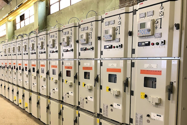
Typical switch gear
Typical switch gear system


Function and uses of switch gear

Consumer equipment is connected to the power system to draw electrical power to perform certain job. In normal conditions a specified amount of current is drawn by the electrical equipment in the system. When fault occurs in the electrical power system, abnormally high current flows through the system. This abnormally high current flow can damage the electrical system equipment like transformer, transmission lines, circuit breaker and power generator. Also this heavy current flow would interrupt the rest of the power system connected to that electrical system. To protect such electrical equipment in the power system like transformer, circuit breaker, generator bus bars and transmission lines from damage, automatic switch gear system is used which is equipped with protective relays and circuit breakers to isolate the circuit in case of any abnormality.

There are certain different relays are connected in the electrical system which are observing line condition all the time. They detects any abnormality on the transmission line. When the fault level exceeds a certain thresh hold level, these relays signals the circuit breaker to break or isolate the circuit. In this way they protects the system from abnormality.

When the fault occurs in the power system, heavy current flow through equipment due to which the equipment get damaged, and the service also get interrupted. So to protect the lines, generators, transformers and other electrical equipment from damage automatic protective devices or switchgear devices are required. In this way the automatic switch gear system isolates the faulty circuit from the healthy circuit or section. The healthy circuit or section continuously in operation and serve without interruption. In this way only faulty circuit is disconnected and no black out for the whole system.

Types of switch gear

There are many types and kinds of switch gear. Switch gear has two types or kind according to construction view point.

  • Outdoor type switch gear
  • Indoor type switch gear

The outdoor type switch gear is located in open are under the sky. Switch gear for above 66KV  are normally outdoor type. The reason behind this is for high voltage very high insulation is required. The insulation between conductor is normally air. So very big spacing is required between high voltage conductors. Such big spacing needs very large building construction. So in such a case it is more feasible to construct such a switch gear outdoor under the open sky.

Outdoor switch gear
Outdoor switch gear


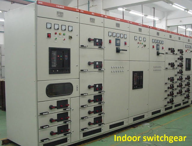
Under 66KV electrical system there is no big issue of insulation and spacing between conductors. For such system indoor switch gear construction is not a big problem. Indoor switch gear units are enclosed in metal panels. They are compact in design. Due to such closed encloser the circuit safety is increased and is easy. Look after is easy for such systems and they are more durable due to weather proofing.
Indoor switch gear
Indoor switch gear

What is inside a switchgear?

Switchgear consists of protection devices like circuit breaker, fusible links, switches, protection relays, bus bars and metering device and equipment for measurement purpose. Switchgear can be outdoor type or indoor type.

What are the different types of switchgear?

According to functionality there are three types of swithgears

  • LV or low voltage switchgear
  • MV or medium voltage switchgear
  • HV or high voltage switchgear

What is a switchgear room?

In electrical control system the switchgear room is the control room that combines the circuit breaker, protection relays, fuses and switches to control electrical power.

What is difference between switchgear and circuit breaker?

Switchgear is a whole system of electrical protection system and control system. Whereas the circuit breaker is a part of switchgear which is used to connect and disconnect the electrical circuit. Circuit breaker works like a high voltage and high current fast switch.

What is HT and LT?

In electrical system HT means high tension and LT means low tension. HV and LV are also used terms for HT and LT. LT or LV is low voltage normally used in our houses and small industries. Whereas HT or HV is the high voltage normally used for transmission of electrical power between cities and countries.

What is MVSG?

MVSG is medium voltage switchgear. Medium voltage is commonly used in industry. Large industrial motors are running on MV which is normally 6KV. To control such power MVSG or medium voltage switch gear is used to switch on and off the system.
Continue reading

Toyota highlander 2021 review and pricing

 Toyota Highlander 2021

Toyota highlander is a sporty-looking xse executive class car which is affordable in its class and features.

Toyota highlander 2021 overview

Toyota highlander 2021 is the latest station wagon from Toyota. Toyota highlander is designed as a family car for executive class which is durable and reliable in its performance. This car comes in standard V6 engine and also the fuel economy hybrid design option is available for people who looks for economy journey. This is an all wheel or 4 wheel drive vehicle which has three row of seats. The last row of seats is designed for kids and younger adults. Toyota highlander is designed with extra feature of safety for driver and passenger.
Toyota highlander 2021


Pricing and models for toyota highlander 2021

Toyota highlander starts from $36K and is going up to $48K for different models and variants. The cheapest one is the L model which starts at $36K. Next is LE model which prices $38K. Toyota highlander hybrid model comes for $40K. XLE model is for $41K. XSE is for $42K. Limited is for $45K and finally the Platinum is for $48K.
Toyota Highlander 2021
Toyota highlander 2021


Toyota highlander 2021 common features

Toyota is always in struggle to provide excellent features in its new models. An average toyota highlander is equipped with heated front seats, sunroof and wireless charging pad for smart phone charging. toyota highlander is equipped with SRS and ABS braking system with anti skid system. It has improved audio stereo audio system with LED on dashboard which is used for rare view camera during reverse gear and also it is equipped with gps navigation system.
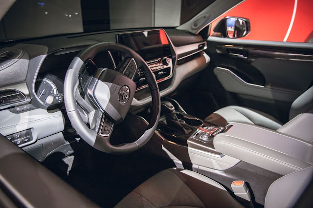
Toyota highlander 2021 interior
toyota highlander 2021 interior


Continue reading

Changan CS85 and CS95 review

Changan CS85 and CS95 cars Introduction and review

About changan cs85 and cs95 china made cars

Changan is a China based car manufacturing company who has assembling plants located in different areas of the world. They have recently established a manufacturing and assembling plant in Pakistan who started manufacturing different variants of changan cars including changan cs85 and changan cs95. Both are excellent cars from changan. The cs85 is a little old model compared to the newer cs95 model.

Changan cs85 cs95
Changan cs85

Changan cs85 and cs95 car engine, transmission and power

cs85 is introduces especially for the Arab world and changan introduces features in cs85 according to the Arab world requirements. Changan cs85 had introduces with 2.0 Liter turbo gas engine with 8 speed automatic transmission. changan cs85 is capable of producing 360 N-m or maximum torque. Changan cs85 is know for its outclass look and glamorous standing in the world. Changan cs85 had introduces in many colors and in an amazing sports car look. Changan cs85 is introduced with star diamond headlights which is providing a dazzling lighting experince.

Changan cs85 cs95
changan cs85 exterior look

Changan cs85 is shipped with Bluecore 2.0T engine and with Aisin 8AT automatic transmission which is making a perfect gear train and is providing excellent acceleration. The changan cs85 has introduced Bosh electronic braking system with provides soundless and perfect safe braking. changan CS85 has all electronic gear shifting which is providing an excellent gearshift with no jerking and smooth operation. Changan CS85 has latest gas type suspension which makes the driving fun and very comfortable in any road conditions.

Changan cs85 cs95
Changan cs85 with 2.0T engine and 8 speed automatic transmission

Changan cs85 had made on the concept of a great latest car. changan cs85 provides excellence in both exterior and interior to make cs85 a symbol of pride. Changan cs85 have 48 suppliers world wide who are working hard to provide excellent service globally. Changan cs85 uses forest air purification system which ensures the supply of pure air all the time inside the car.

Changan CS85 and CS95 safety and security

Changan CS85 is provided with intelligent vehicle system which is Tencent TAI vehicle intelligent system which makes the cs85 very safe on road. In this system cameras and sensors are used in all directions of vehicle to make is safer on road. changan cs85 is provides with IACC integrated adaptive cruise control system which makes cs85 autopilot car.

Changan cs85 cs95 safety
changan cs85 with road safety feature


Continue reading