Here is the Youtube video English version associated to this article:
Here is the youtube video Urdu version:
What is reverse engineering?
Reverse engineering is a term used to dig behind the idea or the concept at which something is build. The reverse engineering reveals the basics of a system on which the system is built.In Electronics the reverse engineering is used to breakdown a build circuit in its basic schematic circuit diagram. This is done to translate the circuit from original system to paper. Once the circuit is got on paper, it is easy then to copy it, circulate it, modify it or enhance it after studying it in detail.
The reverse engineering of small circuit is easy to copy it to paper part by part and note down the components values with care. Anyhow sometimes it is very difficult to understand a pre build circuit when there transformers, some complex coils or some custom made components are used in a circuit. Also it becomes more troublesome when double sided or multi-layer PCB is used. In such a case the best way is to get the concept from a system and design your own circuit with your own concept and idea having same functionality. Anyhow it needs much more knowledge, skill and facility.
Here in the following lines I will show important steps how to reverse engineer a small and simple timer circuit. The circuit itself is very low cost like 1$ but the important thing is to get the concept used in it. Because if one know the concept and the schematic of this circuit, it can be used in big system or circuit when there would be a need.
To reverse engineer a circuit you should know its function, its input, output and supply voltage details. When you have all these details, right them down on a paper and start reverse engineering the circuit details. All the components values you must mention clearly on the paper diagram. All the line connections you should make clearly and take care of jumping wires and connections.
Reverse Engineering the delay automatic on timer board:
Look at the board and count the components carefully. The count will help you to summarize your work and give you help in troubleshooting your work mistakes if happen any.

Look at the copper side of the board also and give a little attention to connections and traces.

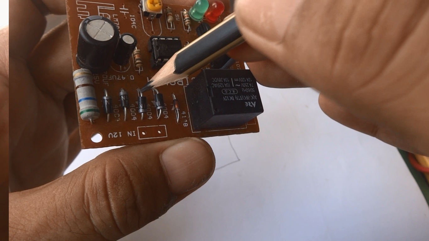
Locate the pin no. 1 of the IC. Also look for the IC number. Then start tracing from IC pin no. 1 where that particular pin is connected. The IC have a notch above pin 1 as you can see in the image blow.

Look that the pin no. 1 trace is connected to the the two solder connections here where I am pointing by pencil. Also the PCB trace is further connected somewhere. We will give attention to all connections to this point.

Upon inverting the board direction, we found that these two soldering connections are two diodes anodes. The diode number where 1N4004. Here we can see four diodes and they form a bridge rectifier. The two anodes junction is negative side supply rail on DC side after bridge rectifier.
Now we are going to draw the pin 1 connection on the paper at IC block. The pin 1 is grounded or connected to negative supply rail.

Now we are giving attention to pin 2. To the pin two a resistor is connected. The resistor value we can calculate from its color code. The resistor color code we will cover in some blog and in some Youtube associated video.

Mention the resistor value that is 18K on the paper with pin 2 on IC block.

Then the next component connected to pin 2 is an electrolytic capacitor. The electrolytic capacitor have two values. Its capacitance in Uf and working DC voltage in Volts. take care of both values.

Mention both values representing the electrolytic capacitor on the paper.

In this way populate all circuit schematics with components and connections with their corresponding values and other details where necessary.

Here is a redrawn circuit schematics using window drawing software. This drawing will give more clear image of the same circuit.


thank you dear Eng
ReplyDeleteYou most welcome dear friend Mohammed.
DeleteThank you.
ReplyDeleteLayout pcb shop address????
ReplyDelete9781595981
buy pcb at this https://www.pcbgogo.com/?code=y site? it's ok ?
ReplyDelete12 volt battery charger cut off circuit battery full charge auto cut off & battery discharge auto on charger circuit diagram please
ReplyDeletehow to purchase online?
ReplyDeleteThanks sir very helpful circuit
ReplyDeleteSir thanks
ReplyDeleteise ke relay wala circuit per bhi aike video bane tafseel se
Hi sir , we need input from 6v solar panel to 4.5 ah battery auto charge cut off indicators ( charge and cutoff ) with adjustable out put voltage ( 4v - 2v ) DC with 5hrs auto off . PCB boards . Please send us how to buy my REQUIRE boards . I hope you send us feedback or any suggestions. Thank you sir.
ReplyDeleteSolar inscet trap circuits with 5hrs auto off light ka video banao sir ji .
ReplyDeleteCircuits ka specification: 6v solar panel , 4.5 ah battery, 3w u.v led 390nm 24no's in parallel. Auto off timer in 5rs . Charge indications,system on indications.
Please chk 560 ohm's resistance position it should be in positive rail the position you fix it will short the circuit
ReplyDeleteThan for perfect learning.
ReplyDeleteAsalaam o Aliakum Respectable Sir very nice Gidences Thanks.Muhammad Khalid Electronice Shope Gizri Clifton karachi.
ReplyDeleteAsalaam o Aliakum Respectable Sir Thanks a Lot,s very nice Gidences.
ReplyDelete