Showing posts with label engine. Show all posts

Monday, March 20, 2017

Generator Alternator electrical repair


Here is the video covering all these details in motion.


House hold generator or alternator is a machine which runs using fuel like gasoline or methane gas and producing line electricity to run electrical appliances like lights, motors and other house hold equipment. The generators are great machines to produce emergency electricity. They work very nicely if they are in their service life. They produce very clean and nice quality electricity suiting to most house hold needs. These machines are very reliable as long as they are good maintained.  An alternator consists of engine and generator or dynamo part. The engine is known as prime mover and running the generator to produce electricity. The dynamo or generator part is electrical part and is producing electricity which is further used.

The alternator or generator has same like synchronous motor construction. It has two major parts like stater or armature and rotor or field. These two parts have winding on them. The stater or armature is producing electricity and the rotor or field winding is producing magnetic field which is necessary to produce electricity. The rotor or field winding is supplied power through slip rings. The slip rings have carbon brushes touches to them and they are providing power all the time to field winding. The field current is known as excitation also.

The carbon brushes are connected to AVR automatic voltage regulator. The AVR is an electronic circuit which is regulating the output AC voltage of the generator produced. AVR is monitoring the generator voltage all the time and regulating it to a certain value. The regulation is achieved by controlling the field current. The field current is directly proportional to the alternator produced emf. So this is actually a closed loop which is monitoring the output all the time and based on output voltage the AVR is controlling the field current to achieve regulated output voltage or line voltage. The AVR output can be adjusted through a potentionmeter or variable resistor to get the appropriate output voltage. That variable resistor is located on the AVR body. One can adjust it using a screw driver.

The wiring to the AVR and from the AVR to the carbon brushes should be firmed and tight. If there will be any loose connection or bad contact in the wiring, the output will be badly effected. Here in the following screens I am showing a problem which occurred in a generator due to loose connection and also demonstrating the output voltage adjustment through AVR. 

There is no out put on the generator output voltmeter. Or zero output voltage when the generator had been started and is running at its normal speed.
Generator no output voltage.
No output voltage at alternator output volt meter read out and output power socket.

The generator is only producing output voltage when its wiring is wiggled. The output voltage produced is not 220V but less as 165V.
Generator output voltage production.
The generator wiring having some problem as it only produces voltage when wiggled.


The following image is showing the output voltage when the generator wiring is wiggled.

The generator is only generating voltage when its wiring harness is wiggled and is pressed.


To diagnose this problem it is required to open the end cover of the alternator where its wiring and connection is located. This cover is held by two screws. Both screws are needed to be removed using appropriate screw driver.


Unscrew both screws to remove the generator end cover. Under this cover generator connections are located.


After opening the end cover keep it side and look at the wiring connections and wiring. Make a visual inspection for any abnormality and damage.

Under the end cover check the wiring and all connections for any damage.


I found an earth or ground wire Yellow and Green loose in its thimble. I found it loose when wiggling on this wire. Removed it and soldered it in its thimble to avoid any loose connection in future.


check for any abnormality, I found this wire loose in its thimble.


Open the screw for carbon brush holder to remove the brush assembly. Check and inspect it for worn out and any damage. Replace if needed. In my case it only needs a little cleaning. Also inspect the slip rings underneath. Clean them using cloth and sand paper if needed.

Alternator carbon brush holder inspection. Inspect for any damage and worn out carbon brush.


Unscrew all screws for AVR to bring it off the generator. Secure all the screw for fixing them back in the end.


Remove the AVR screws to bring it off.


Look at the AVR. You will find a variable resistance or potentiometer to adjust the out put voltage. Adjust this variable to adjust the output voltage using a small screw driver.

Locate the variable resistance of potentiometer on the AVR for output voltage adjustment.


Inspect the circuit board for the AVR for any damage. Repair if you find any loose connection on the board. In my case it was perfect.
Inspected AVR circuit and check it for any damage. Repair if needed.


Now start the generator to adjust output voltage. Be very much careful as you are dealing with 220V AC power. It is lethal and can kill. Don't touch any open wire or connection.


Adjust the output voltage of the alternator by adjusting the potentiometer on AVR using a small screw driver. Keep an eye on the output meter and adjust the potentionmeter till you set it to the desired 220V.


Stop adjustment and fix every thing back when you get the desired 220 V or 230 V output on the generator output panel meter. Use the generator then for your regular use.


Saturday, March 4, 2017

Drive by wire Throttle body cleaning and maintenance


Here is the link to the cleaning process of throttle body and you can watch this procedure in video.


The drive by wire is the newer technology used in cars since 2007 or so. In Toyota it had been introduced in Toyota Yaris model year 2007. In the drive by wire technology the throttle body throttle plate is actuated by an electric motor instead of a mechanical wire and cable arrangement actuated by foot. In the drive by wire system the driver of a vehicle is footing on gas pedal which actuates a set of sensors. They can be some times magnetic sensors and sometimes variable resistors or potentiometers. So by footing on gas pedal a voltage signal is produced proportional to the pressure on the pedal. This voltage signal is feed then to the ECU or PCM of the vehicle. The ECU or PCM is using this signal as input. There are other inputs to the PCM also like MAF sensor, O2 or Oxygen sensor etc. Then ECU or PCM is deciding how much to open the throttle plate to ensure the correct psychometric ratio of fuel and air to get optimum engine performance. In such a case the TPS sensor is acting like a feed back signal sensor to ensure the exact mechanical position of the throttle plate.


The benefit of the drive by wire system is obvious as the ECU or PCM is controlling the throttle plate using an algorithm hence optimum performance and excellent fuel economy is the result. The drive by wire car present much more fuel economy and optimum performance than of the older days mechanical wire arrangement cars were. Also there is another benefit of easy cruise control feature is achieved without installing extra equipment as it was in the case of older mechanical actuated system.


The reason for the optimum performance and better fuel economy is the better control of ECU or PCM on the throttle plate in all driving conditions and situations. The conventional systems is using driver foot force to actuate the throttle plate in the throttle body. So a mechanical wire and cable arrangement is used. Hence the PCM is not controlling air instead it is only controlling fuel quantity to the fuel injectors in such designs. So the system is even a bit mechanical dependent. Whereas in the newer drive by wire system the pcm is controlling the throttle plate hence it controls the quantity of air along with quantity of fuel. By this way a sophisticated and much more efficient control is achieved which results in optimum performance and excellent fuel economy.


Drive by wire system is used in most new car makes and models. They are less pron to dust and dirt accumulation in the throttle body which cases the rough idle and low performance at slow speeds. Anyhow they are having problems when they accumulate dust and dirt. Here in the following lines I am explaining the way to clean and maintain the drive by wire throttle body for a Toyota Camry car.


Drive by wire throttle body cleaning


Locate the throttle body in your car. It is closed to air filter and air intake tube. You should have to remove the air intake tube, the filter box and some times battery also. Also remove the battery one terminal in case if you are not going to remove the battery from the vehicle.


Loose and remove all four bolts which are fastening the throttle body with the air intake. After removing all four bolts you may wiggle the throttle body left and right, up and down and discard it from the air intake and bring it off or the car.


Remove all the electrical connectors and plugs along with wiring harness to be able to remove the air intake pipe and throttle body. Keep the wiring harness side.

Remove the throttle body from the car and inspect it for dirt and carbon deposits accumulation. You will find it very dirty if the car passed more than four years of road like without cleaning the part.


Also see the condition of the air intake mesh. You will find it very dirty also. Clean it and replace the gasket if it is needed.


Bring the throttle body to the washing or cleaning bath and pore some solvent like regular gas or any other solvent of your choice for cleaning.


Clean the dirt and carbon deposits from the throttle body using a nylon brush. Also pore more and more solvent to wash the throttle body further.


Clean and wipe the throttle body using paper towel. By this way you will be able to remove the small dirt and carbon even more. In the result you will get a very cleaned throttle body.


Your throttle body should be cleaned and shine like a new unit. The throttle body should be cleaned to such a degree that the car you are working on should not come again for some four to five years back with same throttle body complaint. Keep in mind that the unsatisfied repair is a sin in the engineering world. Do proper and perfect repair to most reliable degree.


Calibration
The modern throttle bodies in the vehicles need calibration after cleaning them. For the calibration a bidirectional scan tool is required. The scan tool have a procedure to do the zero or factory calibration of throttle body after servicing it. By applying such procedure on can calibrate the throttle body and achieve the ideal idle speed of 600 to 700 rpm. If you don't have a bidirectional scan tool then the other way is to keep the vehicle running and cycle the key for several time. After a few days of use the ECU or PCM will learn the new state of throttle body and will set it to Zero calibration. But the best way is off course to calibrate it using a scan tool.

Here is a link to my other post on another type of throttle boy.
http://diycarmaint.blogspot.com/2017/01/throttle-body-cleaning-maintenance.html

Here is the link to my other throttle body cleaning video on my channel:


Thursday, February 23, 2017

Connecting rod thrust checking using dial gauge method

Connecting rod thrust measurement using dial gauge


Here is a video on youtube on my channel on this subject:


The connecting rod on the crank shaft has a specified clearance to work properly. That clearance is a must to keep the engine in good performance. If the clearance is more, it will create noise and unwanted sound. If the clearance will be less, there will be less oil flow which will create oil starvation condition leads to catastrophic engine failure. If the back and forth clearance of the connecting rod on crank shaft had been increased from the specified amount it is a must to replace the connecting rod or in some worse cases the entire crank shaft. This could be a very expensive repair then and it is normally needed if you run your engine oil for long intervals. The engine oil must be replaced regularly on certain interval. For the oil change interval you must not follow the oil manufacturer recommendation or engine manufacturer recommendation which is giving a very long millage value of say 10,000 to 15,000 mile for a car! Instead you should make your own plan by looking to your engine, environment and the driving conditions of your car. If your car have four cylinders your oil change interval will be more frequent than that of a car having eight or six cylinders. Also if you are living in a hot and dusty environment, your oil change interval will be a little more frequent than the car used in a cold and dust free environment. The third consideration is the driving conditions which means a car running in hilly area had a more tough time to engine. Then the car used in hilly area should change oil more frequently than the same car someone is using in plan area. So considering oil change on a specified interval is a good idea to save expensive engine from a costly repair.

Connecting rod thrust measurement method
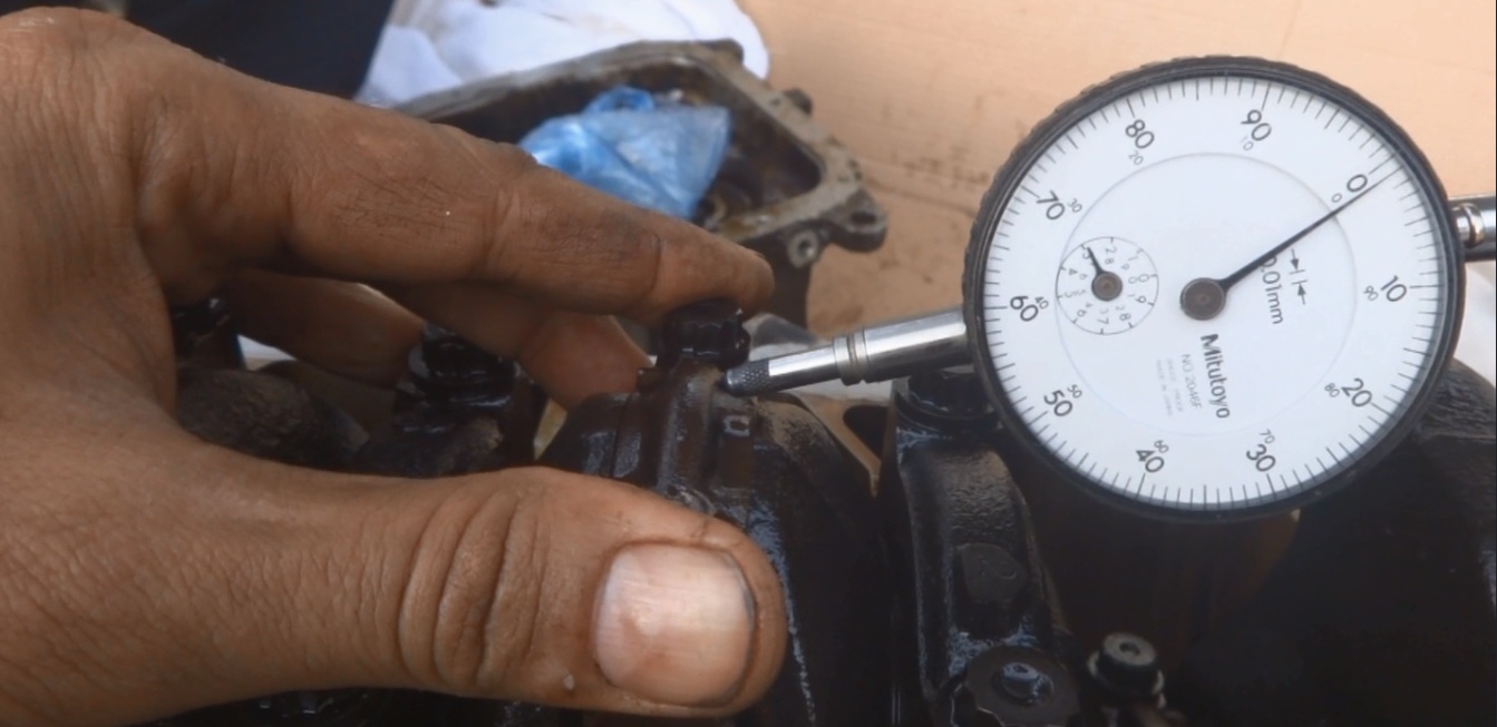
Make the engine upside down and remove bottom cover and sump from the engine. Keep everything as shown in the image below.


wiggle the connection rod bearing back and forth while the dial gauge installed and bring it to the extreme position and make the dial gauge zero here. Then take it to the extreme other side and measure the distance or clearance between the two extremes.


Here is an image from the Toyota factory service manual on the system setup.


Your measurement should be between the specified measurement range specified by the company service manual. The measurement for my case should be between 0.160 and 0.342 mm. In inches it should be 0.0063 to 0.0135 in. The service manual is telling if the thrust measurement is not between the specification, replace the connecting rod or in extreme worst case situation replace the crank shaft.