Saturday, January 30, 2021

Toyota Prius car different ecu location

 Toyota Prius car different ECU location


Location for different ECUs for Toyota Prius

Following schematic diagram depicting locations for different ECUs for Toyota Prius car. There are several ECUs installed for the Toyota Prius car to control various functions to ensure excellent driveability. ECUs communicated to each other using different communication methods depends upon their functionality and working. Toyota Prius is one of the most modern cars from Toyota and has complex electronics and electrical systems involved.
 
Toyota Prius different ECU location

Following are a few main ECUs found in the Toyota Prius car

  1. Certification ECU
  2. Combination Meter
  3. Power source ECU
  4. Tire Pressure Monitor ECU
  5. Gateway ECU
  6. Transponder Key ECU
  7. Transmission control ECU
  8. AC ECU
  9. SRS ECU
  10. Traction control ECU

Friday, January 29, 2021

Toyota Prius transaxle front suspension and drive shafts assembly

 Toyota Prius transaxle front suspension and drive shafts assembly Toyota Prius repair, service manual

Toyota Prius transaxle and driveshafts diagram

Here in the following Toyota Prius transaxle and driveshaft schematic diagram is shown which is focussing on all parts associated with transaxles like axles, driveshafts, suspension, and wheel assembly. Hope this illustration would help many people who are about to repair their Toyota Prius themselves. Also, other small parts like driveshaft seals and the rest of the details are given.

toyota prius driveshaft transaxle and suspension
Toyota Prius driveshaft transaxle and suspension

Toyota Prius suspension and transaxle parts details:

Following are parts for Toyota Prius transaxle and driveshaft assembly:
  1. Snap ring for front driveshaft hole:
  2. Right-hand side assembly for the driveshaft
  3. Oil seal transaxle hybrid vehicle
  4. Left-hand side assembly for the driveshaft
  5. Left-hand side speed sensor front
  6. Clip for suspension
  7. Left-hand side subassembly tie rod end
  8. Left-hand side axle nut for the front wheel
  9. Right-hand side engine undercover
  10. Left-hand side engine undercover

Toyota Prius Toyota Hybrid cvt trans axle gearbox drive

 Toyota Prius Toyota CVT Hybrid transaxle transmission drive gearbox Toyota Prius repair, service manual

Toyota Prius real Toyota Hybrid:

Toyota Prius is one of the real hybrids cars from Toyota which is using hybrid technology and provides the best benefits and great savings on millage over the conventional vehicles of the same class. Toyota Hybrid is equipped with the latest technologies and it is a real modern car from Toyota which is truly hybrid. Toyota Prius uses CVT transaxle technology for drive train which is the best modern technology available on the market. Toyota Prius is cutting on fuel and providing test fuel economy with the best drive pleasure among the other manufacturers.

Toyota Prius Toyota Hybrid transaxle schematic diagram:

Following is the diagram for the Toyota Prius car transaxle. All parts are covers in detail to give a clear understanding of the Toyota Prius hybrid car transaxle.
Toyota Prius transaxle cvt schematic
Toyota Prius transaxle CVT schematic

Parts details for Toyota Prius CVT transaxle for a hybrid:

  1. Breathing plug
  2. Power cable cover assembly
  3. Type T oil seal for hybrid vehicle transaxle assembly
  4. Right-hand side oil seal for Hybrid transaxle
  5.  Tube converter housing of transaxle
  6. SCREW PLUG
  7. COUNTER DRIVEN GEAR SUB-ASSEMBLY
  8. OUTER RACE
  9. DIFFERENTIAL CASE ASSEMBLY
  10. OUTER RACE
  11. SHIM
  12. GASKET
  13. SET PLUG
  14. GENERATOR MOTOR
  15. REVOLUTION SENSOR
  16. WIRING HARNESS
  17. CONNECTOR
  18. SPROCKET DRIVEN GEAR
  19. AND COUNTER DRIVE GEAR
  20. CHAIN
  21. SHIM
  22. THRUST NEEDLE ROLLER BEARING
  23. TRANSMISSION DRIVE
  24. SPROCKET SUB-ASSEMBLY
  25. THRUST BEARING RACE 
  26. PLANETARY RING GEAR
  27. NEEDLE ROLLER BEARING
  28. INPUT SHAFT ASSEMBLY
  29. THRUST BEARING RACE
  30. PLANETARY RING GEAR FLANGE
  31. GENERATOR CABLE
  32. SHIM 


Wednesday, January 27, 2021

Toyota Prius Electrical wiring routing in engine bay part 1

 Toyota Prius Engine bay Electrical parts detail part 1 Toyota Prius repair, service manual

Toyota Prius EM01R0U electrical components under the hood 

Toyota prius wiring routing and components


All components and sensor details for Toyota Prius EM01R0U

1 A/C Condenser Fan Motor

2 ABS & BA & TRAC & VSC Actuator 

3 ABS Speed Sensor Front LH 

4 ABS Speed Sensor Front RH 

5 Air Fuel Ratio Sensor (Bank 1 Sensor 1) 

6 Ambient Temp. Sensor 

7 Brake Fluid Level Warning SW 

8 Brake Master Stroke Simulator Cylinder Assembly 

9 Camshaft Position Sensor 

10 Camshaft Timing Oil Control Valve 

11 Circuit Breaker Sensor 

12 Compressor Assembly (Motor) Inverter 

13 Converter 

14 Converter 

15 Crankshaft Position Sensor 

16 Coolant Heat Storage Tank Outlet Temp. Sensor 

17 Coolant Heat Storage Water Pump 

18 Engine Coolant Temp. Sensor 

19 Engine Hood Courtesy SW

20 Front Airbag Sensor LH 

21 Front Airbag Sensor RH 

22 Front Fog Light LH 

23 Front Fog Light RH 

24 Front Side Marker Light LH 

25 Front Side Marker Light RH 

26 Front Turn Signal Light LH 

27 Front Turn Signal Light RH 

28 Front Washer Motor 

29 Front Wiper Motor 

30 Headlight Beam Level Control Actuator LH 

31 Headlight Beam Level Control Actuator RH 

32 Headlight Assembly LH 

33 Headlight Assembly LH 

34 Headlight Assembly RH 

35 Headlight Assembly RH 

36 Headlight LH 

37 Headlight RH 

38 Horn (High) 

39 Horn (Low)

Tuesday, January 26, 2021

Audi car spark plug design

Audi car spark plugs

The function of the spark plug in the Audi car

A spark plug is usually the end component of the ignition system in any petrol car. Spark plugs must be competent to withstand the high temperature and pressure of the combustion chamber. The ignition occurs billions of times during car engine start condition.

The ability to dissipate heat is the most important characteristic of the spark plug. The central electrode of the spark plug should be hot enough to burn out any carbon accumulation on it during the engine reaches the normal operating temperature. Also, the electrode should not be heated enough that it could burn the central insulator. The central insulator is very important as it separates the central electrode from short-circuiting to ground.
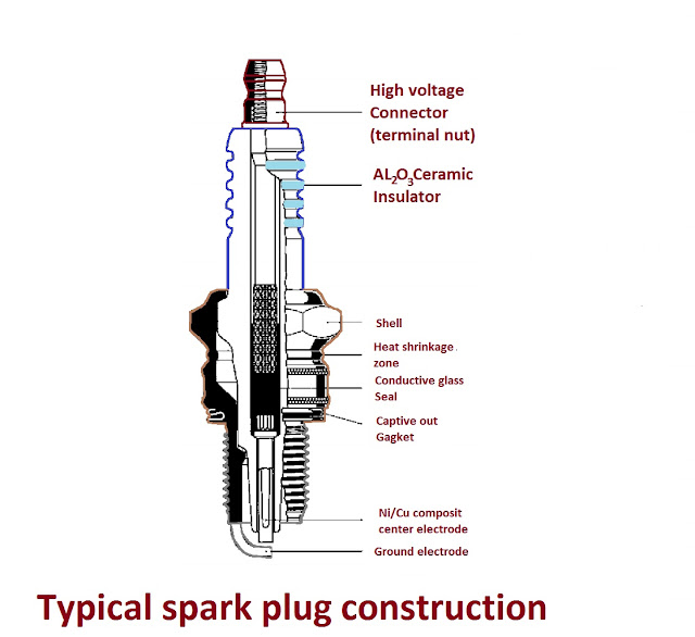
Typical spark plug construction


Cold spark plug

The cold spark plug is referred to as the spark plug which transfers the heat produced by the combustion process fast through the threads to the head of the engine from where it would spread to the cooling system of the car.

Hot spark plug

The hot spark plug is the spark plug that transfers the heat slowly from the combustion process through threads to the engine head from where the heat would be spread to the cooling system of the vehicle.

Types of spark plugs required for different Audi engines

Different engines require different spark plugs. The spark plug has different electrical and physical characteristics. Different manufacturers offer different spark plugs with different characteristics. As engine manufacturers specified the type of plug for their particular engine, it is better to replace the spark plug with the exact characteristics as the can engine manufacturer suggested and specified.

To ensure proper heat transfer from the spark plug to the engine head, it is important to tighten the spark plug into the engine head according to the torque specified by the factory. Values of torques are mentioned in the factory service and repair manuals.

Audi Car ignition system electrical circuit diagram

 Audi Car ignition system electrical circuit diagram

Audi Kettering or CB points ignition system

Kettering ignition system or CB points ignition system was the very common and popular ignition system for the last 100 years. This system was developed or invented by scientist Charles Franklin Kettering in 1906. The Kettering ignition system uses a battery, CB points, capacitor, and distributor for ignition. Before the Kettering system vehicles were using magneto ignition system. In a magneto ignition system, there is no battery and the voltage for the ignition system is produced by a small permanent magnet generator known as a magneto. Magneto ignition system is still used on small engines and motorcycles. Both magneto ignition and Kettering ignition system have their own benefits and limitations. All petrol engines need a spark to combust the air-fuel mixture. For combustion, a spark plug is installed in the engine cylinder head. When the piston reaches the top dead center during combustion stroke, a spark is supplied by the ignition system to combust the air-fuel mixture and an explosion takes place inside the engine cylinder which produces the mechanical power or torque.
Kettering ignition system point ignition circuit


Kettering ignition system working principle
  • Refer to the circuit diagram, when the ignition switch is moved to a close position, electrical energy flows to the primary winding of the ignition coil through the fuse.
  • When the contact breaker points close, the coil gets ground and current flows through the primary of the ignition coil. this flow of current creates a magnetic field around the primary coil.
  • Next, when the points open, the magnetic field collapses, and the energy of the magnetic circuit releases in the secondary coil of the ignition coil. This energy is in the form of high voltage and low current. This is due to the very high number of secondary coil turns of fine wire.
  • Those high voltages are enough to spark on the spark plug.
  • The spark produced is directed to the corresponding cylinder by the distributor. As it is a must to perform the ignition at right time, the distributor performs this job.
  • There is a need for spark advance. The reason for spark advance is needed at high engine rpm. At high engine rpm, the piston moves very fast inside the cylinder. This combustion of air-fuel mixture needs little time to take place. If the spark is applied at the top dead center at high rpm, there will be a delay due to air-fuel mixture combustion. This will degrade the engine performance at high rpm. To meed such a problem, a vacuum spark advancer is used which automatically advances the ignition timing at high engine rpm.

Audi Kettering ignition system and magneto ignition system advantages and disadvantages:


Magneto Ignition System
Advantages
Disadvantages
Advantages
Disadvantages
 Magneto systems don't need a battery to operate. This system generates its own energy. It is suitable for most small engines. The Kettering ignition system needs a battery to operate. Due to battery this system becomes expensive and needs to look after
As magneto is producing its own power. The generation is weak at startup due to less engine speed. This type of ignition has poor starting characteristics. Due to the high power available from the battery during startup, the starting is better and smooth
 In a magneto ignition system, few numbers of components are used which makes the system more reliable and low cost. In Kettering ignition much more components are used which makes the system more complex and complicated. Due to the complexity of the circuit more problems and defects could come in systems and the cost of the system increases.
As the engine speed increases, the generated voltage by magneto also increases due to to which the system performance increases. Kettering ignition system performance decreases with the high engine speed.
It needs multiple coil packs to fire in multiple cylinders for the Kettering ignition systemA single-coil pack with a distributor is enough to spark in multiple cylinders
Magneto systems are normally simple and reliable in construction. They need a permanent magnet, an ignition coil, a point or equivalent electronic switching arrangement to perform the job with simplicity and low cost. 

Kettering ignition system is obsolete now and is replaced with the modern computer or ECU controlled ignition system which needs multiple coils to fire in multiple cylinders.
 

Monday, January 25, 2021

Audi Le Mans quattro Sports car

Audi Le Mans Quattro Sportscar introduction

Audi le mans Quattro

Audi le mans Quattro is a very high-end Audi sports car with a V10 engine. Audi le mans Quattro is made on the concept of Audi R8 car. The Audi R8 won le mans 24 hours race three times. Audi le mans Quattro is an amazing machine which is the excellence of Audi corporation. Audi had produced Le mans Quattro with their years of experience on racing tracks. They developed this car with great effort and the latest technology.

Audi le mans Quattro engine and transmission

Audi le mans Quattro had installed a V10 Biturbo engine with a direct fuel injection system. This car is equipped with an LED headlight on the front whose front glass is clear and provides beautiful light at the night. Audi le mans Quattro is designed with craftsmanship that both the cockpit and passenger seats are perfectly matching the racing track needs. The engine for this car is a five-liter V10 FSI Biturbo engine which is capable of producing 449KW or 610BHP at 6800 rpm. The Audi le mans Quattro is producing a maximum torque of 750N.m of torque which remains constant from 1750 rpm to 5800rpm.
Audi le mans quattro
Audi le mans Quattro