TDA2822 wonderful small and simple audio amplifier
This tutorial will guide you making the most simple and low power audio amplifier comprised of single IC TDA2822. TDA2822 is sometimes refereed as TDA2822M and sometimes simply 2822. This IC provides small power of about 2W per channel from a 5V power source. The power supply is wide range for this chip from 3V to 20V. The wide range of power supply, circuit simplicity, less external components and low price makes this chip ideal for most small application. This TDA2822 is a versatile audio amplifier chip having 8 pin dual inline package and is used frequently in audio Cassatt players, radios, small stereos, PC speakers, telephones and many more applications. This audio amplifier is capable of producing good quality audio with very low distortion so that it could fill up a small room with music waves. This chip has a very low price and available very easily everywhere.
TDA2822M Stereo Amplifier Circuit
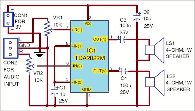
A simplified circuit diagram for such audio amplifier is shown below. The circuit consists of all necessary components for the amplifier requirement with this chip. The component count is so less that anyone having little experience with electronics can create such amplifier circuit.
In the above circuit all components like resistors, capacitors and variable volume controls are connected to different pins of the IC TDA2822M. There components are circuit requirements and they are used to control oscillations and positive feed back in the amplifier circuit. Such components are big in size and heavier so that they can't be constructed inside IC chip. Some chips known as hybrid contains such discrete components inside even. But as this IC chip is monolithic so components are located outside the chip.
Here in this circuit the audio input is provide to pin 6 and pin 7 trough volume controls or variable resistances which acts like atenuators for the audio signal and use to control the gain of the amplifier. Most of the time single shaft stereo type volume control is used in which there are two volume controls are constructed and a single shaft varies both volume controls. Out put to 4 Ohm speakers is provided through two 100UF 25V capacitors. They are AC coupling capacitors and avoid any DC to the speakers from the amplifier. The two inverting input pins pin 5 and 8 are connected together and they are connected to ground through a 1UF 25V electrolytic capacitor to avoid any positive feed back or oscillation in the circuit. At pin 2 of the IC 3V power supply positive is connected which is decoupled with a 10UF 25V capacitor. This capacitor should be located as close as possible to the chip to avoid harmonics and provide good filtration to the power line. Ground or negative terminal of the power is connected at pin 4 to the IC chip.
This circuit has an overall good performance but it is off course and old style class AB amplifier design on chip. New designs uses class D amplifier with great efficiency and less power consumption from battery. Such class D amplifiers is a new technology and are becoming popular in new audio designs for last few years. They are producing much less heat and their heat sink requirement is less and small heat sinks can even do for such amplifiers.
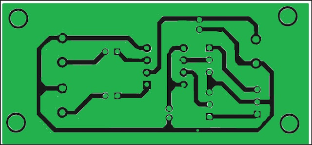
Here is the copper pattern for the pcb for this project. If you are going to do this project, this pcb pattern will help you a lot. This is especially important for university students. The following pcb layout will help identify components locations. The pcb layout is silk printed for this project. The silk print carries all necessary information regarding the whole circuit and project.


Comments
Post a Comment